

MedTronic LDMICRO TUTORIAL
LDMICRO / PIC, AVR, 8051 and ARDUNIO
Programming with LADDER Diagram
Author: Eng.Medhat Saber Ahmed (MedTronic)
Ladder: It is a graphical programming language, in the form of a diagram,
Which, because it is easy to create and interpret and represents physical connections between
Electronic components (sensors and actuators), ends up being widely used
In an industrial environment.
In a simple LADDER diagram, we can find three types of
Basic elements:
1) CONTACT:
It is the element that represents the sensor, i.e. the signal input in the logic control block. can Be one switch, a reflective sensor, a limit switch Or even the contact of an auxiliary relay.

S1, S2
2) COIL (coil): It is the actuating element, that is, the element activated or turned off by the control block

Logical control. It could be a contactor, a
Motor, a lamp, a hearing actuator, etc...
3) MEMORY: or Internal Relay: This is the
Representation of the state of a contact or
Coil in memory, without direct connection to

External elements.
There are also other auxiliary elements that allow you to carry out more complex operations.
Complex tasks, such as timing, counting and data manipulation.
These elements will be discussed in the second part of this tutorial.
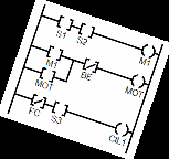
See an example of a LADDER diagram:For this diagram, we have controlOf 3 elements, these being M1, MOT and

CIL1. These elements can beCOILS (ACTUATORS) orMEMORIES (internal relays).Elements S1, S2, BE, VC and S3 onlyAppear on the left side of the diagram,In square bracket format [ ], whichAssumes that they are sensors(Appetizer).In the first line, we observe that theProgram rule defines that output M1 will activate only if the sensorsS1 and S2 are BOTH turned on.In the second line of this program, it is observed that the rule determines that the MOT output will turn on if BE is OFF (Bar means inversion) and if M1 or MOT is activated (At least one of these).In the third line, it is observed that the CIL1 actuator will activate if the FC sensorIs OFF (again look at the bar), and if sensor S3 isActivated. There are also some other important rules about programmingLADDER:1) It is not permitted (or at least recommended) to use the sameCoil (output) on more than one line, as the rules will conflict. PerExample, we could not insert in the previously represented diagramAnother line that would activate the CIL1 actuator. 2) There is the possibility, in some variations of the language, of usingSET and RESET command (on and off) that determines whena given actuator will turn on or off. 3) There are special blocks that allow you to time, detect pulse, edge,Counting and other features. This may vary depending on the languageUsed. LADDER FOR PIC MICROCONTROLLER: THE LDMICRO The LADDER language was born out of the need to facilitate programmingIn industrial environments, referring to a high-level and easy-to-use languageBe used. However, there is a program, (LDMICRO) by Jonathan Westhues,Which allows LADDER programming of microcontrollers, which enablesStudy and implementation of very low-cost controls.This software is very versatile, it does not require installation (just run theLdmicro.exe file in a Windows environment or compatible emulator), and is freeDistribution, as we can see in the window below, extracted from the HELP of theProgram in question:
LADDER FOR PIC MICROCONTROLLER – THE LDMICROThe LADDER language was born out of the need to facilitate programmingin industrial environments, referring to a high-level and easy-to-use languagebe used. However, there is a program, (LDMICRO) by Jonathan Westhues,Which allows LADDER programming of microcontrollers, which enablesStudy and implementation of very low-cost controls.This software is very versatile, it does not require installation (just run theldmicro.exe file in a Windows environment or compatible emulator), and is freeDistribution, as we can see in the window below, extracted from the HELP of the
Program in question:
LDMICRO works as follows: 1) Start the executable program (LDMICRO.EXE). The following screen will be displayed:

It is in this environment that you can generate the LADDER program toMicrocontroller.To insert a coil, press L.
You will notice that the edited line will be built (or complemented) with theIndicated coil. It is allowed to insert more than one bobbin for the same line.
By double-clicking on the created coil, the dialog box will open.

Coil property:
If the coil is defined (in the Source field)As INTERNAL RELAY, the name of the coil
In the ladder diagram will be preceded by theLetter R. Example: If the coil name is new(As in the example above), and if this isSet to Internal Relay, will be displayedAs Renew.If the coil is set to PIN ONMCU, the coil name will be preceded by theLetter Y (in the case of the example, Ynew).
Please note that when entering a contact orCoil, the position of the cursor will be respected(Flashing bar) to define the location of theInsertion. That is, to insert a coil orContact below another, first position the cursor in a horizontal position. To enter a contact:Position the cursor at the desired location, and press C.
To enter a contact:Position the cursor at the desired location, and press C.
Note that a field defined by square brackets --] [--- will appear with the nameXnew. Double click on this item to open the properties box.Contact.
In the source field, you can define whether the contact is an internal relay(Memory). In this case, note that the contact name will be preceded by theLetter R. If set to INPUT PIN (default), the contact is a sensor, aDigital signal input. In this case, the contact name will be preceded by theLetter X (as in the example above: Xnew).If you want to use a coil as a contact (this is possible in ladder),Just activate the OUTPUT PIN option. In this case the name of the inserted elementWill be preceded by the letter Y.The [/] box defines that the input will be negated (with inverted logic),That is, it activates by zeroing the contact, and deactivates by turning on the contact. Practice:
Now try to assemble the following LADDER diagram using the resourcesMentioned above: After editing this program (note that the elements used areOnly and exactly XBOTLIGA, XBOTDESL, YMOTOR). There must not beNo other elements in the program. SAVINGAfter writing your program, save it by clicking FILE -> SAVE AS...Save as a file with the LD extension. SIMULATINGWith the program saved, to simulate the program, click SIMULATE 
SIMULATION MODE, and later on SIMULATESTART REAL TIME SIMULATION.From this moment on, observe in the panel at the bottom of the window theState of contacts and coils. Just DOUBLE CLICK on the itemTo change your state.Test by changing the state of the sensors, and see if the program works. COMPILING. To generate a HEX file from this program, simply follow theseSteps: 1) Click on SETTINGSMICROCONTROLER and define whichMicrocontroller to be used. For better operation, click SETTINGSMCU PARAMETERS and set the clock crystal valueUsed. The default is 4MHz. 2) Now double-click on each DIGITAL IN or DIGITAL OUT element of theBottom of the window, associating eachCONTACT or COIL to a pin of theMicrocontroller. 3) Now click on COMPILE COMPILEAS.. And indicate the name of the file to beGenerated. IMPORTANT: Don't forget to

Place the HEX extension. Ex: PROG.HEX.If you do not enter the extension, it will beHarder to find it later with the programRecording (EPIC, ICPROG, etc...) Most used commands:Insert new line shift V or shift 6Insert a semicolon commentDetects rising edge/Detect falling edge\Timer to turn off FTimer to turn onTimer to turn on T retentiveIncremental counter UDecremental counter ICircular counter JCompare equality =Compare whether it is bigger >Compare whether it is smaller <Compare whether it is greater or equal.Compare whether it is less or equal,Insert L COILInsert Contact CInsert E counter resetLoad variable with value MInsert sum + operationInsert subtraction operation -Inserts multiplication operation. *Inserts division operation DAnalog P reading Exercises: Try running the following LADDER programs on the microcontroller: Exercises:Try running the following LADDER programs on the microcontroller:1)Note: To insert a line, use SHIFT + VNote the CORRECT names of the items involved:XB1: Button 1 of the two-manual system.XB2: Button 2 of the bi-manual system.XEMERGENCY: Emergency button. If OK, it is at 1. Pressed at 0.YMORSA: VISE actuator, which holds the part. Call with a bot. press.YPRENSA: PRESS actuator, only turns on when pressed. the 2 buttons.YBUZZER : Audible alert. It must indicate emergency triggered (at zero).RPISHING: Auxiliary relay that will flash every 400 ms. 2) Try adding a part sensor to the above system. If the part does not Is detected, the walrus should not start. 3) Now also add a beep indicating whether a button has been Pressed and the part was not placed. 2) Try creating the ladder scheme for a garage door. Use theFollowing elements: XBOTAO: Remote control button.XOPEN: End of travel sensor that determines that the gate isOpenXCLOSED: End-of-stroke sensor that determines that the gate isClosedXIMPACTO: Impact sensor. Detects that the gate has collided with something.YMOT_OPEN: Motor that moves the gate towards opening.YMOT_FECHA: Motor that moves the gate towards closing.Use your creativity. Simulate the program in the ladder environment, and on the stationw/ PIC microcontroller. Good job. PART 2: DESCRIPTION OF LDmicro COMMANDS 1. Comment insertion2. Contact insertion3. Rising edge (pulse) detection4. Falling edge (pulse) detection5. Power-on timer6. Shutdown timer7. Retentive power-on timing8. Increment counter9. Decrement counter10. Circular counter11. Comparison – equal12. Comparison – different13. Comparison – bigger14. Comparison – greater or equal15. Comparison – smaller16. Comparison – less than or equal17. Open circuit18. Closed circuit19. Main (general) control relay20. Insert coil21. Enter counter/timer reset22. Data movement (attribution)23. Addition (16 bits)24. Subtraction (16 bits)25. Multiplication (16 bits)26. Division (16 bits)27. Shift Register28. Table (look-up)29. Table of values (linear association)30. String formatted by serial31. Insert serial output32. Insert input via serial33. Activate PWM34. Insert A/D reading35. Sets value as persistent in EEPROM Translation of LDmicro's HELP, document by Jonathan Westhues, carried out by MedTronic, in December 2023
Post a Comment