
What is on the Arduino Board?
Among all Arduino boards available on the market, the easiest and commonly used board is Arduino UNO. Some of these boards may have a different look and feel, but all have some standard components. So, let us discuss its fundamental components here.
Arduino UNO
It is a simple and commonly used prototyping board suitable even for beginners to get along with electronics. Being the basic one, it is essential for every electronics developer to know its different components.
UNO comes with an ATmega328P microcontroller. It has two variants: one has a through-hole microcontroller connection and the other has a surface mount type. In the through-hole model, you can replace its chip with a new one in case of any error.
Arduino UNO is an 8-bit microcontroller with the AVR architecture, and it offers different features and capabilities.
UNO comes with a total of 14 digital input-output (I/O) pins that you can use as input or output. Out of these 14 pins, you can use the six pins for producing PWM signals. Each pin on this board works at 5V and has a current of 20mA.
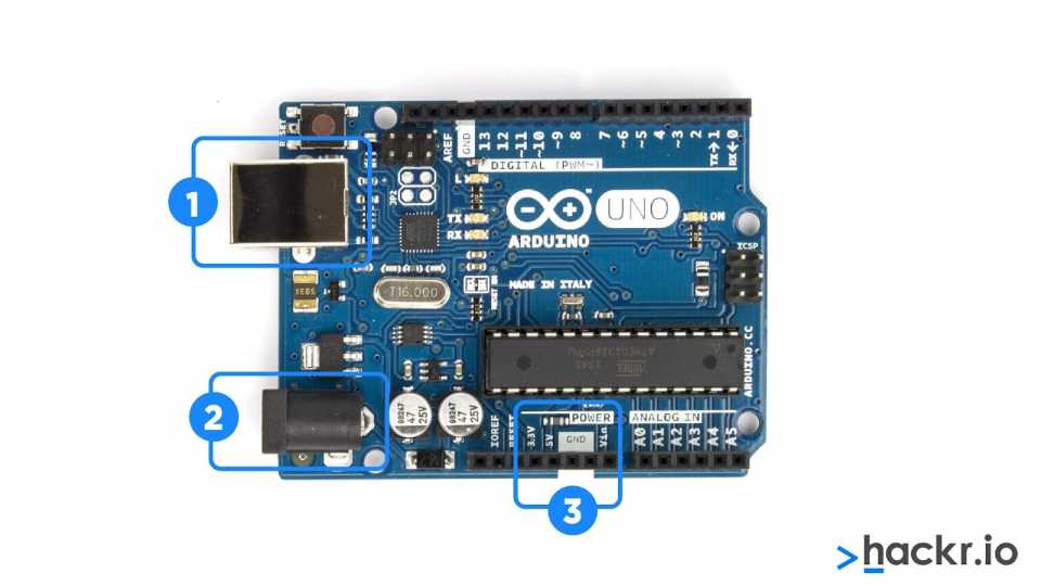
- We always need a power source to make txhe board work. You can power this board using a USB connection to your computer, and you can either use a wall power supply that will terminate in a barrel jack. In the above image, (1) specifies the USB and (2) specifies the barrel jack.
You can even load the code using a USB connection onto your Arduino board.
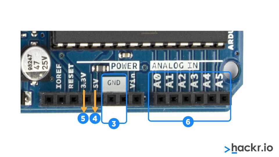
The above image shows the following:
- GND (3): GND stands for ‘Ground,” which is used to ground your circuit.
- 5V (4) & 3.3V (5): The 5V pin can be used to supply five volts of power, and the 3.3V pin can be used to supply 3.3 volts of power.
- Analog (6): These pins labeled from (A0 to A5) are known as Analog pins. They will convert an analog sensor to a digital one.

The top right of the above image highlights the 14 I/O pins that can perform specific functions, as stated below:
- With
pins 0 and 1, you can carry out serial communication to receive and
transmit serial data. You can use them to program the Arduino board and
communicate with a user via the serial monitor.
- With pins 2 and 3, you can provide external interrupts. These pins trigger an external event.
- Six pins (3-11) are used for 8-bit PWM output.
- Pins 10, 11, 12, and 13 are for SS, MOSI, MISO, and SCK, respectively, especially for SPI communication.
- Pin
13 comes with a built-in LED connection. When this pin is set to HIGH,
the LED is turned on, and when it is LOW, the LED is turned off.
- AREF stands for Analog Reference, used to set an external reference voltage ( 0 -5 Volts).
- At
the top left of the above image, (10) specifies the reset button. This
button connects the reset pin to the ground and restarts the uploaded
code. Pressing the reset button in case of failure will allow you to
test your code multiple times.
- The number (11) specifies the Power LED Indicator, which will light up when powering your Arduino to a source.

- In the above image, (12) specifies the TX RX LEDs, where TX stands for transmit and RX for receive.
These are used for serial communication. These LEDs provide visual
indications while receiving or transmitting data using Arduino.
- (13)
specifies the Integrated circuit, otherwise known as the brain of
Arduino. You can see the IC type mentioned on the top of the IC.
- (14) specifies the voltage regulator, which helps control the amount of voltage supplied to the Arduino board. It acts as a gatekeeper, preventing an extra voltage from entering the circuit. Also, it comes with some limits, so do not connect the Arduino to more than 20 volts.
إرسال تعليق