All About LEDs
In this article, we’ll be using basic electronics theory and terms, so if you’re not familiar with Ohms law, voltage, current, and other such terms, take a quick read of our Analogue Electronics Crash Course first.
Working Principle of LEDs
A LED, as the name implies, is a special type of diode, one that emits electromagnetic energy (light) when activated. We won’t be going right down to the nitty-gritty physics behind semiconductor technology but a diode consists of a P-N junction. A P-N junction is two semiconducting materials, one which is processed (‘doped’) to have a great number of electrons (N for negative as electrons are negatively charged particles), and the other which is doped to have less electrons, or ‘holes’ where the electrons are missing (P for positive as an absence of electrons creates a positive charge). When a current passes through this junction, electrons jump from the N side to the P side to fill the holes as electrons move around the circuit and as the electrons cross this gap, energy is given off (in the case of LEDs, light energy). The lower level physics is a little more complicated than that, but suffice to say that you can control the wavelength of the energy emitted (wavelength corresponds to a colour of visible light) by altering the construction of the LED and the materials used to create the P-N junction.

By User:S-kei - File:PnJunction-LED-E.PNG, CC BY-SA 2.5
Speaking of colours, LEDs are available in a wide variety of colours, shapes, sizes and intensities (brightness), however, something that often confuses people is why Blue LEDs are usually more expensive than other colours of LED. It’s because of the fact that whilst colours such as Red, Green, and infrared LEDs have been around for almost half a century, blue LEDs have only been around for a decade or two because they require a different material and process for construction (Gallium nitride GaN). Nowadays though you can get almost any colour of LED including non-visible spectrum LEDs such as infrared (as used in remote controls) and ultraviolet.
Construction of an LED
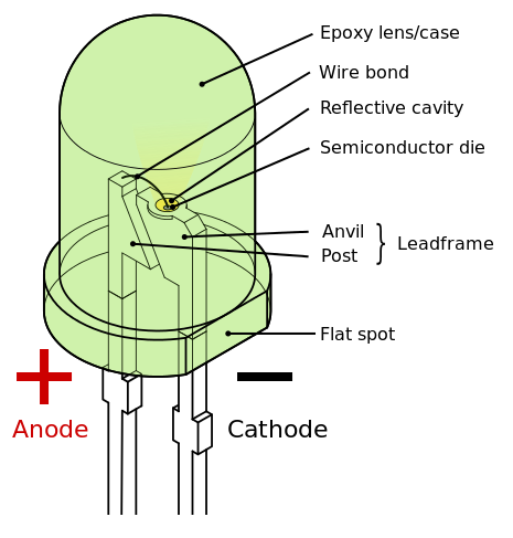
An LED is a fairly simple device, it consists of an epoxy body (either clear or coloured) with the semiconductor die in the middle attached to two leads. The two leads on a diode are known as the Anode and Cathode. The Anode of the LED is the positive lead, and the cathode is the negative lead. On standard through-hole LEDs, the body will have a flattened edge on one side, the lead on this side is the cathode and is usually also the shorter lead. LEDs, like diodes, are polarised devices which mean they will only allow current to flow in one direction. If you insert an LED into your circuit incorrectly, it won't break, it just won't light up.

By Inductiveload - Own work by uploader, drawn in Solid Edge and Inkscape., Public Domain
So that’s nice to know and all, but how do you actually go about using LEDs? Let’s take a look.
Using LEDs
Whilst there are many different types of LEDs for different applications including automotive and home lighting, today we’re going to focus specifically on the standard LED types used in electronics. These LEDs are available in various forms such as 10mm-3mm through-hole packages, and SMD packages, however, the principle is the same. When using LEDs, there are 2 important characteristics which need to be considered in order for them to work properly. As LEDs are just a special type of diode, many of the principles discussed here also apply to diodes.

By Afrank99 - Own work, CC BY-SA 2.0
Forward Voltage:
In order for an LED to emit light, a certain voltage needs to be applied across the LED. This is known as the ‘forward voltage’, or to put it another way, the LED will cause a loss of a fixed voltage across it, and this is required for light to be produced. For most LEDs, this is between 1.7V-3.3V depending on the colour of light emitted (a Blue LED requires a higher forward voltage than a Red LED).
Forward Current:
As with an electronic component, an LED is a load on a circuit and when a circuit is completed, current flows. The forward current of an LED refers to the amount of current it will consume when operating at its intended brightness. For most LEDs, it’s between 15mA-20mA and it’s important to take note of this as allowing an LED to draw too much current will dramatically shorten its life (a Blue LED hooked up directly to a 12V supply without any current limiting will be destroyed in a few seconds). Because of the extremely low current draw vs. brightness, LEDs are replacing traditional forms of lighting in almost every area due to their efficiency.
Protecting LEDs with a Current Limiting Resistor:
So the forward current and voltage are important, so how do we ensure that our LEDs are being powered safely and efficiently? Well since most power supplies are going to be greater than the forward voltage, and be cable of supplying more than the forward current, we need to create an additional load on our circuit, so we use a resistor.

If you’ve read our Analogue Electronics Crash Course, you’ll have a fair idea of how resistors work, but let’s recap quickly. A resistors job is to (you guessed it) resist the flow of electrons (current), and any resistive load will cause a voltage drop across it. So we can use a resistor to limit the current being supplied to our LED and calculating the resistance required is a simple matter of applying Ohms law: V=IR (Voltage = Current x Resistance). So let’s dig in!
Let’s take the following characteristics of a typical Red LED with a forward voltage of 1.8V and a forward current of 20mA. For the simulation, we’ll be using a 9V power supply.
So we will be using Ohms law to find the resistance value we need so we re-arrange the formula to be R=V/I, we just need to find the voltage drop across the resistor and the current to give us the resistance. If the LED drops 1.8V across it, another 7.2V is going to drop across the rest of the circuit (our resistor), so V=7.8. Seeing as we want to limit the current through the circuit to 20mA, I=0.02 (Amps). So now we can divide 7.2 by 0.02 to give us: 360. Therefore we need a current limiting resistor of 360 Ohms.
And that’s all there is to it, now you can work out the resistor value required to drive any LED. Try solving another problem using V=IR where the LED has a forward voltage of 2.2V, a forward current of 18mA, and the power supply is a 12V supply, and post your answers in the comments below!
Controlling the Brightness
If you want to adjust the brightness of an LED, you can increase the current limiting resistor to reduce the current to the LED and reduce the brightness, however, make sure that you don’t go below the calculated resistor value. This is fine to permanently fix the brightness, however, unlike incandescent bulbs (traditional style light globes using a stranded filament) you can’t adjust the brightness just by changing the voltage to the LED. You’ll get a weird response and it won’t be a nice smooth change. Instead, to control the brightness of an LED you use PWM.
PWM is discussed in more depth in our other tutorials, however, the concept is quite simple. You turn the LED on and off quicker than the human eye can perceive as individual flashes, and the ratio of on/off time in a certain frequency is perceived by the human eye as an increase/decrease in brightness. For more detailed info about how PWM works,
Using Multiple LEDS: Series vs. Parallel
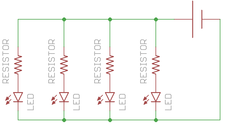
So using one LED is fine, but what about if we want to connect more than one LED up to a power supply and have them all light up? You’d think that we could simply connect the one after the other with a resistor at the end, this is known as connecting them in Series. However, if we did this, each LED has a voltage drop, which means that each consecutive LED has less and less voltage available, which means the LEDS will get dimmer and dimmer as you go down the circuit. What we need to do is connect them in Parallel as shown:

This way, every LED is in its own loop of the circuit, and no LED is receiving more power than another. But be warned, say you need a 360 Ohm resistor for a single LED, as shown above, you can’t use a single 360 Ohm resistor for all of the LEDs because that value is designed to limit the current to only 20mA, but if you have multiple LEDs connected up in parallel, the current draw for them adds up, so we need to recalculate for a current draw of all the LEDs combined.
![]()
RGB and Digital LEDs
As exciting and all as a single colour LED is, a big upside of LEDs is that because of their small size, you can combine multiple LEDs into a single package to create an RGB (Red Blue Green) LED which creates colours across the visible spectrum thanks to additive light. Using these LEDs is simple, they have a common lead (either the Cathode or the Anode) and a separate lead for each colour which you can use to control each colour channel independently. These are great, but imagine using a lot of them and the amount of pins it would take to control them. In recent years we've seen the development of digitally addressable LEDs which pack an RGB LED plus a tiny controller chip into a standard package and allows you to control huge strips of them with a single microcontroller pin! For more info on these types of LEDs, check out our NeoPixels with Particle tutorial.
What Now?
That’s pretty much all of the basics on using LEDs, you can go and create your own spectacular devices involving light and wonder. If you have any other questions, let us know in the comments below. Happy making!

إرسال تعليق